Assemble a DuinoStamp
Now that you have the parts and tools required, lets solder!
 |
Cut down the header strip . The headers come packaged as a strip of 40. Using your side-cutters, cut between the posts to make the following sizes:
You should have an extra 6 pin connector now, it's not required for this kit, save it for a rainy day. |
|
|
Install the 28 pin socket. Place the socket on the PCB, ensuring you align the notch in the socket with the notch on the PCB legend. Flip the board over, and making sure the socket is completely inserted, solder all 28 leads. |
|
|
Install the Resistors. Bend the resistor leads down from the body by 90°. Insert the resistors into their places. The 10K resistor (Brown, Black, Orange, Gold) goes at the end of the socket, in the location marked 10K. The 1K resistor goes above the socket in the location marked 1K. You may install the resistors in either direction. Flip the board over and solder all 4 leads. Using your side-cutters, trim the leads flush with the solder-joints. |
|
|
Install the Capacitors . Both capacitors should be placed in their outlined places. You may install them in either orientation. Flip the board over, solder all 4 leads, then trim all 4 leads. |
|
|
Install the Pin 13 LED . Place the LED with it's longer (anode) lead on top (close to the text 'GND AREF'. Flip the board over, solder the leads, then trim the leads. |
|
|
Install the Pin 13 Resonator. Place the resonator into it's 3-pin location below the socket. You may install it in either direction. Invert the board, solder all three leads, and trim. |
 |
Place the Headers. Place the headers (with their long-pins down) into your breadboard as follows: Three rows above the center, place an 8 pin header. Leave three empty columns, then place a 6 pin header. Two rows below the center, place a 6 pin header. Leave three empty columns, then place the remaining 10 pin header. |
|
|
Solder the Headers. Place the DuinoStamp onto the headers. Solder each pin. Be careful not to apply heat for too long, you could melt the pin, your breadboard, or both. |
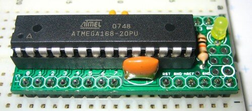 |
Install the ATmega. Straighten the ATmega's pins by gently pushing them in to a 90° angle to the body. Gently push the ATmega down into it's socket; make sure you line the ATmega's notch with the socket's notch and the board legend's notch. |
| Optional: Use the remaining pair of three-pin headers to create an ICSP socket. |


You're all done!